
LACP between two peers of Cisco Nexus switches
Created: 2021-03-07 23:13:03 | Last modified: 2021-03-10 08:38:13Access: Read | Views: 214 | Rating: N/A | Tags: cisco
LACP between two peers of Cisco Nexus switches example
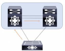
We have two peers of Nexus switches in two different data centers and these are connected together using a DCI (Data Center Interconnect) with 10Gb/s transceivers. Each of the data center switches are configured as single homed devices using VPC (Virtual Port Channels) to allow LACP redundancy. We are wanting to link these peers switches back to back,.
We have had issues getting them to keep the links active when in LACP mode. These are the configurations we have used on each of the switches.
We have followed Cisco's best practices guide here
- Each peer of switches must be in different VPC domains
- Each peer of switches should to use different VPC peer link IP ranges.
- Each peer of switches should to use different VPC peer links VRFs
We had issues with the VPC staying up as soon as VLANs were added to the allowed list, to fix this we needed to add the following to the DCI link Port Channels
# Enable BPDU Filter
spanning-tree bpdufilter enable

# to fasten port state forwarding mode
spanning-tree port type edge

# Enable spanning-tree root guard on port channel
spanning-tree guard root
Here is a cut version of the configuration we used between a peer of Nexus N3K series switches to a peer of Nexus N9K-9300 series switches
DC1 - Switch 1
vrf context vpc-keepalive
vpc domain 1
  peer-switch
  peer-keepalive destination 172.16.33.11 source 172.16.33.10 vrf vpc-keepalive

interface port-channel5
  speed 10000
  description DC Link
  switchport mode trunk
  switchport trunk allowed vlan 2000
  spanning-tree port type edge
  spanning-tree guard root
  spanning-tree bpdufilter enable
  vpc 5

interface Ethernet1/52/1
  speed 10000
  description DC Link - A
  switchport mode trunk
  switchport trunk allowed vlan 2000
  channel-group 5 mode active
  no shutdown
DC1 - Switch 2
vrf context vpc-keepalive
vpc domain 1
  peer-switch
  peer-keepalive destination 172.16.33.10 source 172.16.33.11 vrf vpc-keepalive

interface port-channel5
  speed 10000
  description DC Link
  switchport mode trunk
  switchport trunk allowed vlan 2000
  spanning-tree port type edge
  spanning-tree guard root
  spanning-tree bpdufilter enable
  vpc 5

interface Ethernet1/52/1
  speed 10000
  description DC Link - B
  switchport mode trunk
  switchport trunk allowed vlan 2000
  channel-group 5 mode active
  no shutdown
DC2 - Switch 1
vrf context vpc-keepalive-2
vpc domain 2
  peer-switch
  peer-keepalive destination 172.16.34.11 source 172.16.34.10 vrf vpc-keepalive-2

interface port-channel5
  description DC Link
  switchport
  switchport mode trunk
  switchport trunk allowed vlan 2000
  spanning-tree port type edge
  spanning-tree guard root
  spanning-tree bpdufilter enable
  speed 10000
  duplex full
  vpc 5

interface Ethernet101/1/47
  description DC Link - A
  switchport mode trunk
  switchport trunk allowed vlan 2000
  speed 10000
  duplex full
  channel-group 5 mode active
  no shutdown
DC2 - Switch 2
vrf context vpc-keepalive-2
vpc domain 2
  peer-switch
  peer-keepalive destination 172.16.34.10 source 172.16.34.11 vrf vpc-keepalive-2

interface port-channel5
  description DC Link
  switchport
  switchport mode trunk
  switchport trunk allowed vlan 2000
  spanning-tree port type edge
  spanning-tree guard root
  spanning-tree bpdufilter enable
  speed 10000
  duplex full
  vpc 5

interface Ethernet101/1/47
  description DC Link - Chorus
  switchport mode trunk
  switchport trunk allowed vlan 2000
  speed 10000
  duplex full
  channel-group 5 mode active
  no shutdown
Testing
Test and confirm that the VPCs come up correctly, this should be done on each of the switches
show vpc brief

show spanning-tree vlan 2000
